
We usually discuss synchronous vs asynchronous reset. Readers need to beware that “asynchronous reset” may refer to:
Let’s talk them one by one.
First, let’s look at the verilog code:
  always @ (posedge clk or posedge arst) begin
    if (arst) begin
      data <= 1'b0;
    end else if (cen) begin
      data <= din;
    end
  end
The code holds nothing special. data will be reset to 1'b0 when arst asserted, and back to normal operation if arst de-asserted. Since reset have higher priority over clock, the Q output will be cleared even without the edge of clock. After synthesis, you will surely get a Flip-Flop register with async reset.
The time async reset asserted is usually not import, since the output of register will be guaranteed after reset. However, if async reset is released on the time near the clock edge, the register may enter a metastability state. Metastability means unpredictable output, and possibility of fail. So, even async reset have timing requirement similar with sync reset. This is a common misunderstanding for new designers. The required timing relationship is called recovery and removal time check.
Recovery check ensures reset signal goes stable at least “recovery time” before the active clock edge. Like “setup time” for sync pin, right? Removal check ensures reset signal should only change at least “removal time” after the active clock edge. Similar with “hold time”. Note that the “recovery and removal time” only defined for the de-assertion of sync reset. Since assertion of async reset will take charge of the output, regardless the clock edge.
The natural behavior of async reset pin self brings no problem, as long as it meets the recovery and removal time requirement. The real problem is the violation of timing requirement. For example, if the reset signal comes from an external pin, nothing could ensure when it arrives. Other example including use locking indicator of PLL as async reset. Reset comes from other time domains should also be considered as async. We already know that even async reset signal need to satisfy the recovery and removal time, or it may cause the design fail.
To avoid the problem of async reset signal, we usually have an “asynchronous reset synchronizer” circuit. Here we give two most used:
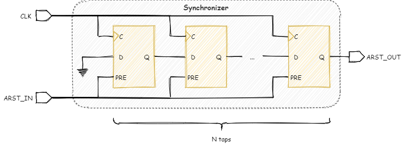
Several registers are chained together. Those registers have async reset pin connected to external reset input. When ARST_IN asserted, all registers and ARST_OUT goes to 1 immediately. After ARST_IN de-assert, it takes several clock ticks before ARST_OUT goes back to 0. To clean up the metastability cased by the unknown arrive time of async reset, the chain need at lease 2 FFs. More taps of pipeline helps to reduce the mean time between failures (MTBF).
Will it solve all the problem of asynchronous reset? Let’s look at the blow circuit:
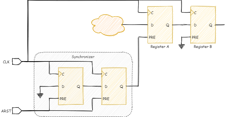
The output of Register A goes to Register B. They both working on same clock so expecting synchronous data. Keep in mind that ARST to register B’s D pin is a valid data path (ARST -> PRE -> Q -> Register A PRE -> Register A Q -> Register B D). Reset source “run through” a long path and reached a synchronous pin. Since reset source is working asynchronously, this is a design violation to get it captured on a flip-flop which is expecting synchronous data. When designing import control logic such as FSM, carefully implementation should be noticed.
Another synchronize is shown blow:
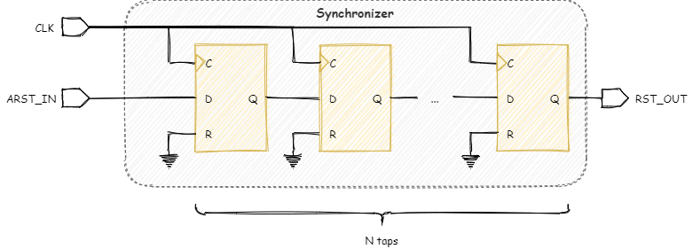
A simple general purpose single-bit CDC circuit may satisfy our requirement. RST_OUT will be asserted and de-asserted synchronously with CLK. So it solves the async reset run through issue. The synced reset could be safely connected to async or sync reset pin of registers. Comparing with 1, it will not work without the presence of clock.
| Async Reset | Sync Reset | |
|---|---|---|
| Synchronizer #1 | OK | NOK |
| Synchronizer #2 | OK | OK |
If you can decide the reset type to use for your registers, don’t worry too much. Each can effectively implement the design and archive the purpose of reset. Each has its own advantages and disadvantages. If you need to reset a specification region of logic before a clock starts up (or even with no clock), sync reset can’t help. If reset signal also arrives asynchronously, synchronizer type 1 remains the only option.
ASIC designers usually choose async reset. It saves the amount of transistors. While Xilinx recommends sync reset for their FPGA device. This may because they already implemented sync reset for most of their primitives. Tools can optimize the design deeper using the interchangeability of sync reset.
Here give the brief summarize of reset type and synchronizes choose:
| Gated Clock | No Gated Clock | |
|---|---|---|
| Async Reset | Synchronizer #1 | Both |
| Sync Reset | Not possible | Synchronizer #2 |
Detailed reset strategies will be talked in another post.
© 2021 Kele, CC BY-NC-SA 4.0